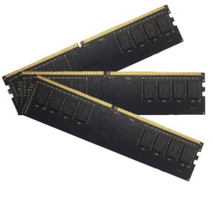
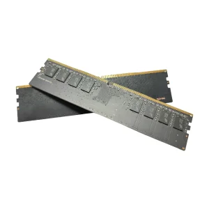
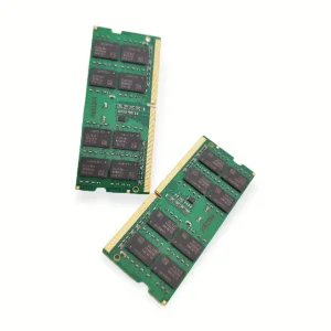
Premium aerospace-grade Rogers-hybrid laminates and matching high-speed memory systems configured for critical USA infrastructure applications.
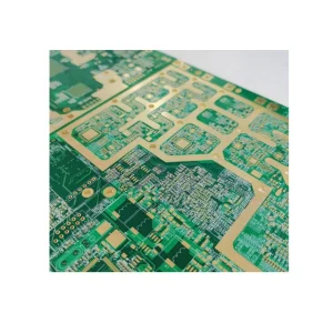
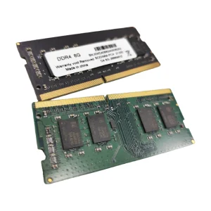
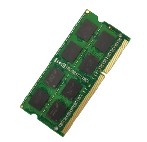
The demand for high-frequency printed circuit boards (PCBs) in the United States has experienced an exponential surge, primarily driven by aerospace engineering, defense communications, autonomous vehicle ADAS (Advanced Driver Assistance Systems), and the national deployment of mmWave 5G and nascent 6G infrastructure. US designers are at the forefront of RF (Radio Frequency) technology, developing products that operate at multi-gigahertz frequencies where signal integrity, minimal loss tangent ($D_f$), and highly stable dielectric constants ($D_k$) are absolutely non-negotiable.
However, the domestic US manufacturing landscape faces unique challenges. While local quick-turn shops excel at rapid prototyping and low-volume aerospace assemblies under ITAR oversight, scaling these sophisticated Rogers, Taconic, or PTFE (Teflon) multilayer builds to commercial volumes within the domestic border remains cost-prohibitive for many OEMs. Consequently, leading system designers seek a robust hybrid supply chain that combines localized engineering with cost-efficient offshore volume capabilities.
RF circuits require laminate materials engineered with strict precision. The table below highlights standard materials utilized in high-frequency multilayer stack-ups:
| Material Type | Typical Dk (10GHz) | Typical Df (10GHz) | Best Suited Applications |
|---|---|---|---|
| Rogers RO4003C / RO4350B | 3.38 - 3.48 | 0.0021 - 0.0037 | Base station antennas, LNBs, RF power amplifiers |
| PTFE (Teflon) Glass Reinforce | 2.20 - 3.00 | 0.0009 - 0.0015 | Military airborne radar, satellite communication transceivers |
| Shengyi FR4 High TG170 (Hybrid) | 4.3 - 4.6 | 0.015 - 0.020 | Cost-effective hybrid support layers in multilayer boards |
| Taconic (RF-35 / TLX Series) | 3.50 | 0.0018 | Power amplifiers, couplers, automotive collision avoidance |
Navigating the global electronics supply chain demands a delicate balance of local engineering support and high-scale manufacturing efficiency. While US engineering firms develop high-frequency PCB layouts, they rely heavily on global suppliers to manufacture their complex stack-ups, such as Shengyi FR4 combined with Rogers 4000 mixed pressure assemblies. This hybrid structure lowers overall substrate costs while maintaining RF performance on critical outer layers.
This is where Celtrix Memory Technologies and partner factories play a pivotal role. By optimizing production lines to handle hybrid material bonding (thermoset/PTFE press-cycles), Chinese high-tech manufacturers provide substantial information gain and engineering optimizations to US system integrators. By aligning local US representatives with advanced domestic factories, customers benefit from seamless DFM (Design for Manufacturability) analysis, competitive prototyping cycles, and scalable mass-production pathways.
A trusted global manufacturer and exporter specializing in high-frequency computing substrates, DRAM integration, and high-performance memory modules.
Celtrix Memory Technologies Co., Ltd. is a professional DDR5/DDR4 memory and high-speed PCB assemblies manufacturer dedicated to delivering high-performance DRAM and RF substrate solutions for global customers. Since its establishment in 2017, the company has focused on the research, development, manufacturing, and customization of premium memory and high-frequency systems for consumer, industrial, enterprise, and embedded applications.
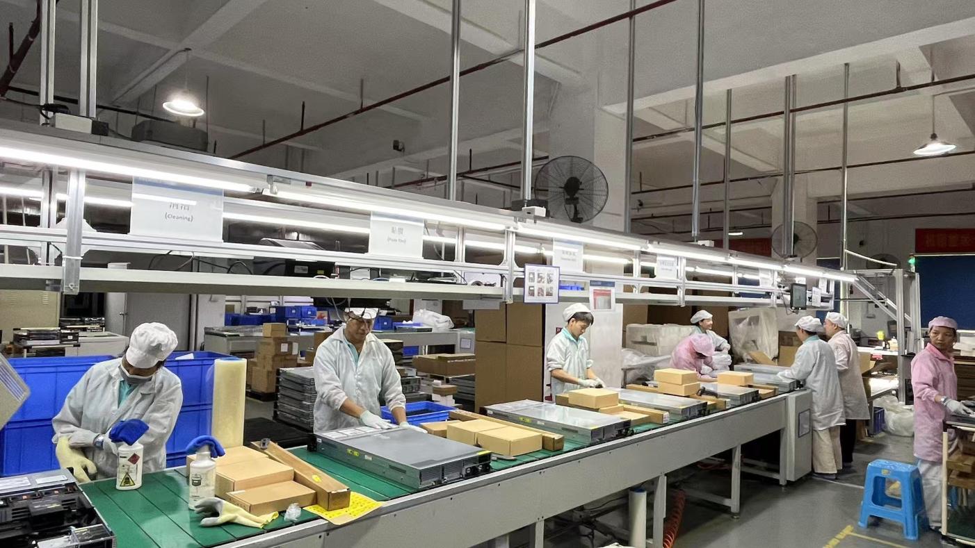
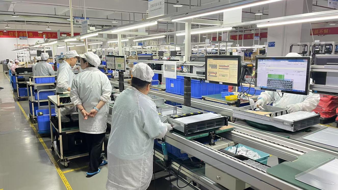
With a modern manufacturing facility covering 28,600 m², Celtrix integrates advanced production equipment, automated SMT assembly lines, and strict quality management systems to ensure reliable high-speed product performance and consistent manufacturing standards.
Thorough incoming inspection of high-frequency laminates, copper foils, and premium DRAM chips.
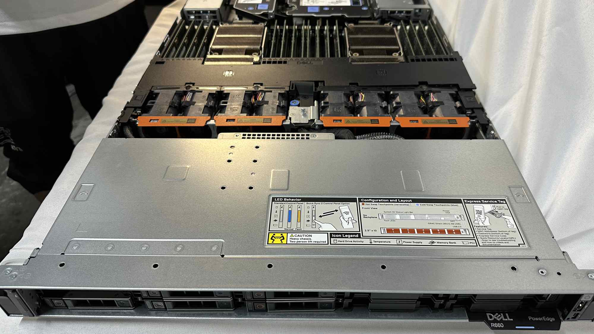
Real-time optical alignment check during multi-layer lamination and impedance-controlled plating.
Advanced optical inspection testing for trace width, path spacing, and solder paste consistency.
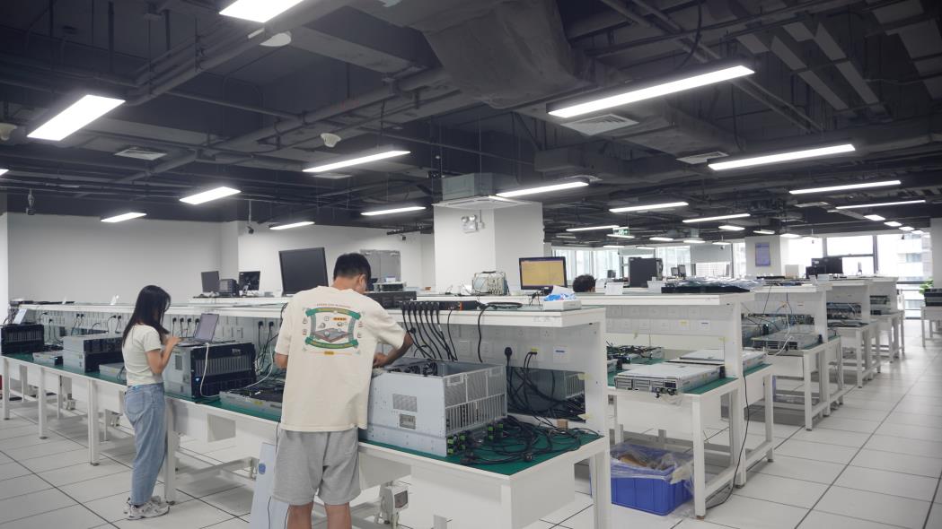
Extreme thermal cycling, aging tests, and final quality control checks prior to export sealing.
The company has accumulated 9 years of industry experience and 7 years of export experience, serving customers across more than 50 countries. Our R&D capability includes independent research and development with OEM/ODM support, backed by 142 specialized R&D engineers who released 168 new products last year alone. Customization options include Logo Printing, Capacity Customization, Heat Spreader Design, SPD Programming, Label Design, Packaging Customization, and Private Label Services.
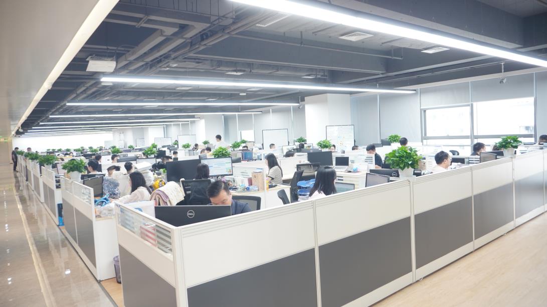
Expert analytical guidance on managing RF loss factors and ensuring reliability in high-speed, multi-layer designs.
At high operating frequencies (typically above 5 GHz), electronic signals travel along the outer surface of the copper trace due to the "skin effect." Surface roughness of the copper foil directly increases signal path resistance, resulting in signal attenuation. System designers must request specialized low-profile copper options (such as VLP - Very Low Profile, or RTF - Reverse Treated Foil) when sourcing high-frequency PCBs.
Additionally, controlling impedance parameters ($Z_0$) requires precise coordination of trace geometry, substrate height, and dielectric constant uniformity. A deviation of just 5% in trace width can lead to significant signal reflections, causing data loss in high-speed computing modules or target misalignment in radar systems.
As frequency increases, heat generation within the dielectric and conductors climbs rapidly. Sourcing engineers must evaluate the thermal conductivity ($TC$) of high-frequency laminates. For instance, Rogers 4350B features a thermal conductivity of $0.62\text{ W/m/K}$, which is nearly double that of standard FR-4. Incorporating thermal vias, heavy copper planes, or bonding the PCB to an aluminum backplate helps mitigate heat accumulation, ensuring continuous operation in aerospace and critical data transmission environments.
Essential insights for US procurement managers, hardware engineers, and systems integrators.
A hybrid stack-up combines high-frequency layers (such as Rogers 4000 series) on the signal routing surfaces with low-cost FR-4 layers in the inner cores. This strategy drastically reduces raw material costs while keeping the high-frequency signal pathways isolated on low-loss substrates, offering an optimal balance between performance and budget.
High-frequency PCBs often operate in high-temperature environments. If the CTE of the copper trace and the underlying dielectric laminate are misaligned, thermal expansion differences can cause mechanical stress, trace delamination, and crack plated through-holes (PTH). Rogers and PTFE laminates are designed with a low CTE (close to copper) to maintain dimensional stability across varying temperatures.
Yes. Celtrix DDR4 and DDR5 memory modules undergo strict compatibility testing across mainstream US enterprise server chipsets (Intel Xeon and AMD EPYC). They feature ISO 9001 quality compliance, automated AOI inspection, and thermal stress testing to ensure long-term reliability in high-capacity workstations and server environments.
We offer comprehensive customization, including custom PCB panel layout design, logo screen-printing, SPD programming for customized memory profiles, heat spreader design, capacity changes, and bespoke packaging for bulk commercial deployment.
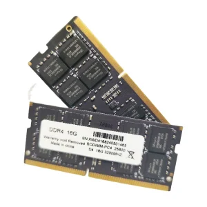
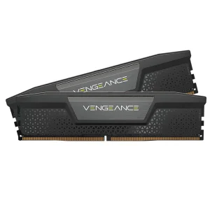
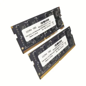
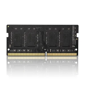
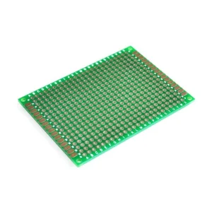
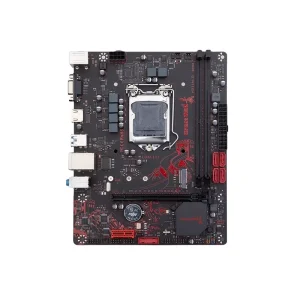
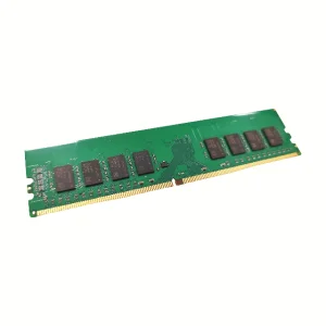
Explore our full line of memory modules, motherboards, and double-sided prototyping boards for US labs and manufacturers.
Consult with our engineering team for free DFM analysis, hybrid material stack-up reviews, and fast prototyping options.
Send Inquiry Now Celtrix Memory